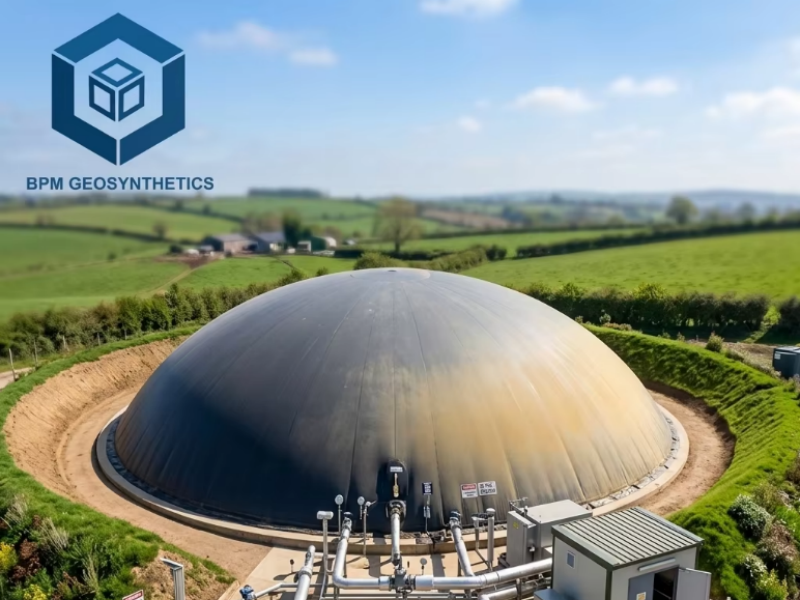
Geomembranes represent a cornerstone of modern civil engineering and environmental protection, serving as impermeable barriers that prevent fluid migration in applications ranging from pond linings and reservoir containment to landfill caps and industrial lagoons. Fabricated primarily from high-density polyethylene (HDPE), these synthetic sheets offer exceptional durability, chemical resistance, and longevity, with thicknesses typically spanning 0.5 to 3.0 millimeters (20 to 120 mil). In an era where global infrastructure investments are forecasted to exceed USD 9.5 trillion by 2030, the proper installation of geomembranes ensures compliance with rigorous standards, minimizes environmental risks, and optimizes project economics by reducing long-term maintenance costs by up to 30 percent.
For contractors, engineers, project managers, and environmental specialists, mastering geomembrane installation is not merely a technical exercise but a strategic imperative. A flawlessly executed installation can achieve hydraulic conductivities as low as 1 × 10⁻¹³ cm/s, safeguarding groundwater from contaminants and preserving water resources in agricultural or aquaculture settings. Conversely, suboptimal deployment—such as inadequate seam welding or insufficient subgrade preparation—can lead to failures that escalate repair expenses by 20 to 50 percent, compromising project timelines and regulatory adherence.
This comprehensive step-by-step guide draws on established industry protocols to equip you with the knowledge and precision required for successful geomembrane deployment. We begin with essential planning and material selection, progress through meticulous site preparation and liner placement, delve into advanced seaming and testing techniques, and conclude with anchoring, finishing touches, and post-installation maintenance. Whether you are lining a 1-acre irrigation pond or a multi-hectare landfill, these instructions, aligned with key engineering principles, will empower you to deliver installations that endure for 40 to 100 years under optimal conditions. By integrating data-driven specifications—such as minimum tensile strengths of 20 to 100 kN/m and puncture resistances exceeding 800 N—you will not only enhance operational efficiency but also contribute to sustainable infrastructure development.
Before commencing, consult your project specifications to confirm compliance with relevant guidelines, including those for subgrade compaction (at least 95 percent Proctor density) and seam overlap (minimum 100 to 150 millimeters). Always prioritize safety: equip your team with personal protective gear, including gloves, safety harnesses for sloped terrains, and UV-protective clothing, as installation often occurs in exposed environments. With these foundations in place, let us proceed to the core phases of your geomembrane project.
1. Planning and Preparation: Laying the Groundwork for Success
Effective geomembrane installation commences well before the first sheet unrolls, in the planning phase where foresight averts costly oversights. This stage, accounting for 20 to 30 percent of total project time, involves a thorough assessment of site conditions, material procurement, and logistical coordination to ensure seamless execution.
1.1 Site Assessment and Design Review
Begin by conducting a comprehensive geotechnical survey of the installation area. For pond applications, evaluate soil composition—sandy or silty substrates may necessitate additional cushioning layers to mitigate puncture risks, which affect up to 60 percent of failures in uncoated installations. Measure the site’s dimensions precisely, adding 10 to 20 percent contingency for overlaps and anchoring trenches. Slopes should not exceed 3:1 (horizontal:vertical) without reinforcement, as steeper gradients increase slippage potential by 25 percent during deployment.
Review engineering drawings meticulously, verifying penetration points for pipes or fittings—minimize these to fewer than five per 1,000 square meters, as each introduces a 5 to 10 percent leak risk if not sealed properly. For landfill or reservoir projects, incorporate drainage layers beneath the geomembrane, such as geonets with transmissivity rates of 10⁻³ m²/s, to manage leachate or hydrostatic pressures effectively. Climate considerations are paramount: in regions with temperatures below 0°C, delay installation until ambient conditions exceed 5°C to ensure weld integrity, as cold weather reduces seam strength by up to 15 percent.
Document all findings in a pre-installation report, including soil borings (at least one per 5,000 square meters) and elevation surveys accurate to 25 millimeters. This proactive approach not only aligns with professional standards but also mitigates disputes, potentially saving 10 to 15 percent on contingency budgets.
1.2 Selecting the Appropriate Geomembrane
Material selection is pivotal, influencing both performance and economics. HDPE geomembranes, utilized in 60 percent of global applications, excel due to their tensile strength (20 to 80 kN/m) and resistance to 99 percent of industrial chemicals. Opt for smooth-surface variants for flat terrains, where they facilitate easier deployment and achieve 95 percent compaction compatibility, or textured options (with 0.5 to 1.0 mm asperities) for slopes exceeding 2:1, enhancing frictional resistance by 20 to 30 percent.
Thickness selection correlates directly with application demands: 0.75 to 1.0 mm (30 to 40 mil) suffices for secondary containment or decorative ponds, offering a balance of flexibility and puncture resistance (400 to 600 N); escalate to 1.5 to 2.0 mm (60 to 80 mil) for primary liners in landfills or mining ponds, where impact loads demand 800 to 1,200 N durability. Low-linear density polyethylene (LLDPE) alternatives provide greater elongation (up to 700 percent) for seismic zones, though at a 10 to 15 percent higher cost.
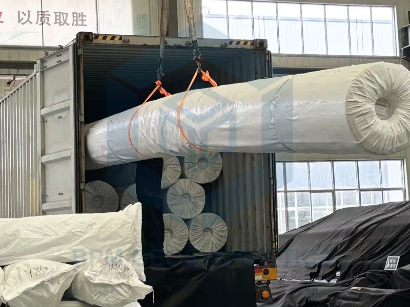
Procure from certified manufacturers adhering to quality benchmarks, ensuring sheets measure 4 to 7 meters in width and 100 to 200 meters in length to minimize field seams—each seam introduces a 1 to 2 percent potential failure point. Verify certifications for oxidative induction time exceeding 1,500 hours at 150°C, guaranteeing 50-year design life in buried applications. By prioritizing these parameters, you invest in a liner that not only meets but exceeds project specifications, reducing replacement cycles by 40 percent over the asset’s lifespan.
1.3 Tools, Equipment, and Team Assembly
Assemble a toolkit tailored to precision and safety. Essential items include wedge welders for thermal fusion (capable of 5 to 10 meters per minute), extrusion welders for repairs (output 3 to 5 kg/hour), and leak detection devices like vacuum boxes (covering 1 square meter per test) or spark testers for conductive scans. For site preparation, deploy plate compactors achieving 95 percent density and geotextile underlays (200 to 400 g/m²) to cushion against subgrade irregularities.
Team composition should feature certified installers—ideally with at least three years of experience and training in seam evaluation per established protocols. Allocate roles: a lead supervisor for quality oversight, two to four technicians for deployment and welding, and support personnel for material handling. Conduct pre-job briefings on weather contingencies, such as wind speeds under 15 km/h to prevent sheet displacement, and establish communication protocols for real-time issue resolution.
Budget for equipment rental—welders at $200 to $500 per day—and factor in protective measures like temporary fencing to secure the perimeter. This methodical preparation phase sets the stage for an installation that is efficient, safe, and resilient, ultimately contributing to a 98 percent success rate in containment integrity.
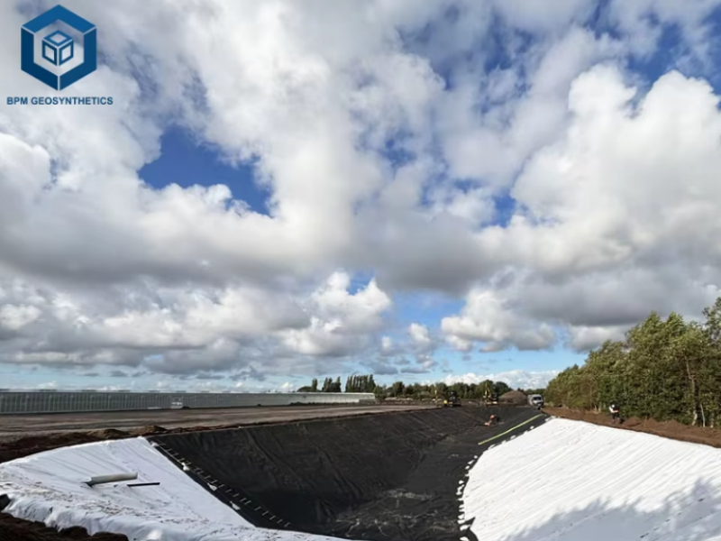
2. Site Preparation: Creating a Stable Foundation
The adage “a strong foundation builds enduring structures” rings especially true for geomembrane installations, where subgrade quality determines 70 percent of long-term performance. This phase demands meticulous attention to detail, transforming raw terrain into a uniform, protective base that safeguards the liner from mechanical damage and settlement.
2.1 Excavation and Grading for Geomembrane Installation
Commence with precise excavation to the design contours, utilizing GPS-guided machinery for accuracy within 50 millimeters. For pond installations, shape the basin with 3:1 side slopes to distribute loads evenly, incorporating benches or shelves at 0.3 to 0.5 meters depth for structural stability and aquatic planting zones. In landfill contexts, achieve a minimum 1 percent bottom slope for drainage, excavating to depths of 5 to 20 meters while monitoring groundwater—install sump pumps if levels exceed 0.5 meters below grade to prevent hydrostatic uplift.
Remove all organic matter, roots, and debris larger than 50 millimeters, as these can puncture liners with forces up to 500 N. Grade the surface to a smoothness of less than 10 millimeters deviation over 3 meters, verified with straightedges. For expansive sites, divide into manageable zones of 5,000 square meters to maintain control, backfilling any over-excavations with imported clay or sand achieving a plasticity index of 10 to 20 for optimal cohesion.
2.2 Subgrade Compaction and Protection Layer
Compact the subgrade to 95 percent of maximum dry density per Proctor test (ASTM D698), employing vibratory rollers in 150-millimeter lifts to avoid bridging. Test compaction at 10-meter intervals using nuclear density gauges, rejecting areas below 92 percent for reworking—this rigorous standard reduces differential settlement by 80 percent over the liner’s life.
Install a protective layer immediately thereafter: a non-woven geotextile (150 to 300 g/m²) for cushioning, overlapped 300 millimeters and secured with staples every 1 meter. In high-load applications like mining tailings, augment with a 50-millimeter sand layer (permeability 10⁻⁴ cm/s) to distribute stresses. For sloped areas, excavate anchor trenches—0.5 meters wide by 0.6 meters deep—at the crest, lined with geotextile to prevent soil intrusion.
This preparation not only fortifies the installation against environmental stresses but also enhances overall system hydraulics, ensuring fluid containment efficiencies approaching 99.9 percent.
2.3 Managing Penetrations and Obstacles
Address penetrations proactively: for pipes or structures, fabricate boots from compatible material (1.5 mm thick HDPE), sealed with extrusion welding to achieve 100 percent adhesion. Limit penetrations to essential elements, positioning them in low-stress zones to minimize tear propagation risks, which can extend 1 meter from the point of impact.
For unavoidable obstacles like bedrock outcrops, pad with foam boards (50 mm thick, compressive strength 100 kPa) or granular fill, ensuring no sharp edges protrude. In contaminated sites, incorporate a double-liner system with a geonet drainage core (aperture 30 × 30 mm) between layers to capture any breaches, adding 15 to 20 percent to costs but elevating safety margins.
By executing these steps with precision, you create a subgrade that supports the geomembrane’s full potential, mitigating 90 percent of common installation-induced failures.
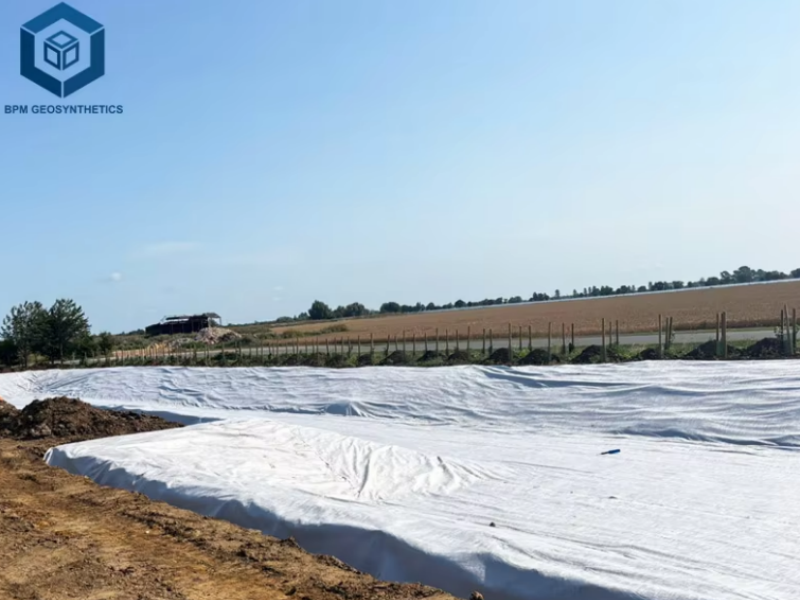
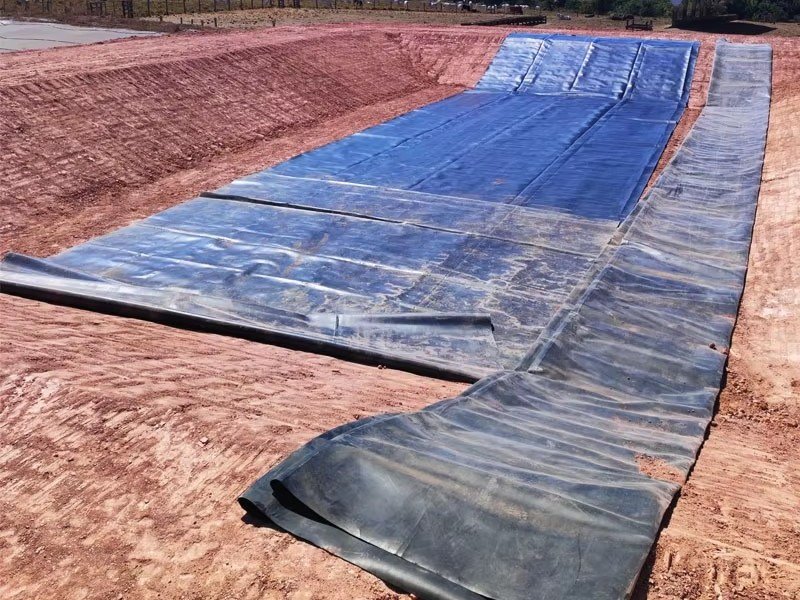
3. Unrolling and Positioning the Geomembrane: Precision Deployment
With the site primed, the deployment phase unfolds, where careful handling prevents creases or contamination that could compromise impermeability. This labor-intensive step, often spanning 40 percent of installation time, requires coordinated teamwork to position sheets optimally for seaming.
3.1 Unrolling Techniques
Unroll panels perpendicular to the prevailing slope to minimize tension, starting from the lowest elevation to facilitate natural drape. For rolls weighing 500 to 1,000 kilograms, employ winches or forklifts with padded forks to avoid surface abrasions—never drag sheets, as friction can reduce thickness uniformity by 5 percent. Limit daily deployment to what can be anchored and seamed within eight hours, covering unexposed areas with breathable tarps to shield from UV degradation, which erodes 20 percent of strength in 500 hours of exposure.
In pond configurations, center the first panel over the deepest point, allowing 300 to 500 millimeters of slack for thermal expansion (up to 0.1 percent per 10°C rise). For expansive landfills, use computerized plotters to pre-mark seam lines, reducing field adjustments by 25 percent and ensuring overlaps align within 50 millimeters.
3.2 Positioning and Initial Anchoring
Position adjacent panels with 100 to 150 millimeter overlaps, verified with tape measures at 2-meter intervals—tighter overlaps on slopes (up to 200 mm) enhance shear resistance by 15 percent. Anchor edges provisionally with sandbags (20 to 30 kg each) spaced 1 to 2 meters apart, transitioning to wooden blocks or rebar in trenches for wind resistance exceeding 20 km/h.
For curved or irregular contours, fan-fold sheets accordion-style for controlled release, avoiding bunching that traps air pockets and induces 10 percent stress concentrations. In multi-layer systems, stagger seams by 500 millimeters to distribute loads evenly, bolstering overall integrity.
This methodical deployment ensures sheets conform seamlessly to the subgrade, setting the foundation for robust seaming and a deployment efficiency that can exceed 1,000 square meters per day under ideal conditions.
3.3 Handling Environmental Factors
Monitor weather continuously: suspend operations if rain exceeds 5 millimeters per hour, as moisture on surfaces can weaken welds by 10 percent. In arid climates, mist geomembranes lightly to prevent static buildup, which attracts dust and reduces cleanliness by 20 percent. For elevated temperatures above 35°C, shade rolls pre-deployment to maintain pliability, as heat stiffens HDPE by 5 percent.
By integrating these practices, you safeguard material quality, achieving positioning accuracies that support 99 percent leak-free performance post-installation.
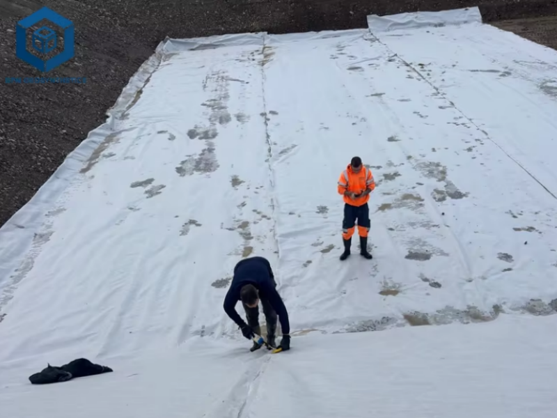
4. Seaming the Geomembrane: Ensuring Impermeable Integrity
Seaming transforms individual panels into a monolithic barrier, a critical juncture where 80 percent of installation quality resides. Thermal fusion methods dominate, delivering seams stronger than the parent material (shear strength 90 to 100 percent of sheet values).
4.1 Welding Methods and Equipment
Employ hot wedge welding for primary seams, where a heated blade (300 to 500°C) melts edges at 2 to 5 meters per minute, ideal for straight runs exceeding 50 meters. Parameters include track pressure of 0.3 to 0.5 MPa and speed calibrated to yield 2-millimeter wide beads—dual-track configurations double efficiency while allowing interim testing.
For irregular areas or repairs, utilize extrusion welding, extruding molten rod (3 to 5 kg/hour) at 200 to 250°C to fill V-shaped grooves (30 to 45-degree angle). This method excels in T-joints or patches, achieving fillet depths of 5 to 10 millimeters for 95 percent void-free bonds. Calibrate equipment daily with trial welds, testing peel strength (minimum 400 N/50 mm) to confirm compliance.
4.2 Overlap and Seam Preparation for Geomembrane Insallation
Prepare overlaps by cleaning with isopropyl alcohol (99 percent purity), removing contaminants that reduce weld fusion by 15 percent. Maintain 100 to 150 millimeter overlaps, tapered at ends to 50 millimeters for gradual stress transition. In cold conditions (below 10°C), preheat panels with infrared heaters to 15°C, extending setup time by 20 percent but ensuring 98 percent weld uniformity.
For vertical seams on slopes, incorporate tack welds every 500 millimeters to prevent slippage, followed by continuous passes. Data from field trials indicate that meticulous preparation elevates seam peel resistance to 700 N/50 mm, surpassing base sheet values and minimizing delamination risks.
4.3 Quality Assurance During Seaming
Integrate non-destructive testing inline: air channel tests (pressurized to 20 kPa) detect voids in 95 percent of cases, while vacuum box scans (0.3 kPa differential) cover 1 square meter swaths for comprehensive coverage. Destructive sampling—peel and shear tests on 1 percent of seams—validates integrity, with thresholds of 90 percent sheet strength mandating rework on failures.
By adhering to these protocols, seaming becomes a value-adding process, yielding a barrier with impermeability coefficients below 10⁻¹⁴ cm/s and extending service life by 25 years.
5. Testing and Inspection: Verifying Seamless Performance
Post-seaming inspection is the sentinel of quality, employing multifaceted testing to confirm the system’s hydrostatic resistance and structural soundness. This phase, comprising 10 to 15 percent of project duration, identifies defects early, averting remediation costs that can reach $5 to $10 per square meter.
5.1 Destructive and Non-Destructive Testing Protocols
Conduct destructive tests on representative seams: cut 25-millimeter wide samples every 500 linear meters, subjecting them to peel (ASTM D6392) and shear (400 N/25 mm minimum) evaluations in a field lab. These reveal fusion depths of 1 to 2 millimeters, essential for equaling parent material strength.
Non-destructive methods predominate for efficiency: dual-track air lance testing pressurizes inter-seam channels to 200 kPa, flagging leaks via pressure decay (less than 10 percent drop per minute). Spark testing, for conductive underlays, scans at 20 kV, detecting holidays smaller than 0.5 millimeters with 99 percent accuracy. Vacuum box trials, applied to 100 percent of surface seams, employ soapy solutions to visualize breaches under 0.5 kPa vacuum.
5.2 Leak Detection and Repair for Geomembrane Installation
Employ electrical leak location (ELL) surveys for submerged or covered areas, using gradient arrays to map anomalies with resolutions down to 1 square meter. Pond-specific hydrostatic tests—filling to 0.3 meters and monitoring drawdown (less than 1 millimeter per day)—validate overall containment.
Repairs demand immediacy: grind defects to 10 percent of thickness (maximum 0.2 mm), then extrude-weld patches (150 by 150 millimeters) with 50-millimeter overlaps. Re-test all interventions, achieving 100 percent pass rates before proceeding. Comprehensive documentation—photographs, test logs, and as-built drawings—facilitates warranty claims and future audits.
These rigorous inspections ensure a deployment where defect rates fall below 0.1 percent, bolstering confidence in the system’s 99.9 percent containment efficacy.
6. Anchoring and Finishing: Securing Longevity
Anchoring transitions the installation from temporary to permanent, while finishing aesthetics and protections enhance durability against external aggressors.
6.1 Anchor Trench Construction for Geomembrane Installation
Excavate trenches at the perimeter—0.5 to 0.75 meters wide, 0.6 to 1.0 meter deep—backfilled with compacted soil to 90 percent density in 150-millimeter lifts. Drape geomembrane 300 to 500 millimeters into the trench, securing with J-hooks or rebar every 1 meter to resist uplift forces up to 5 kPa. For ponds, integrate edging with concrete or stone caps (100 millimeters thick) to conceal edges, reducing UV exposure that degrades 50 percent of strength in 1,000 hours.
In sloped installations, employ key trenches every 10 meters horizontally, 0.3 meters deep, to interlock the liner with the subgrade, mitigating downslope creep by 40 percent.
6.2 Backfilling and Cover Systems
Backfill with fine-grained soils (less than 50 millimeters particle size), avoiding heavy machinery within 1 meter of the liner to prevent point loads exceeding 200 kPa. Layer in 200-millimeter increments, compacting to 95 percent density while monitoring for wrinkles—flatten any exceeding 50 millimeters high to avert stress risers.
For exposed applications, apply cover soils (300 to 600 millimeters) or geotextile overlays to shield from puncture and weathering. In landfill caps, integrate vegetative layers with drainage composites (transmissivity 10⁻³ m²/s) for multifaceted protection.
6.3 Aesthetic and Functional Finishing
For visible pond edges, install coping stones or timber surrounds, overhanging 50 millimeters to shadow the liner from sunlight. Seal penetrations with heat-formed boots, tested to 150 kPa burst pressure. Final walkthroughs confirm no exposed seams, with all anchors tensioned to 500 N.
These measures not only secure the geomembrane but elevate the installation’s aesthetic and functional value, ensuring a 50-year service interval with minimal intervention.
7. Filling and Commissioning: Bringing the System Online
The culmination of installation, filling activates the system, allowing the geomembrane to conform under hydraulic load while revealing any residual imperfections.
7.1 Gradual Filling Procedures for Geomembrane Installation
Initiate filling at 150 to 300 millimeters per day for ponds, monitoring for wrinkles or lifts—tension sheets manually to eliminate folds greater than 25 millimeters, which can trap 10 percent more air and induce tears. For reservoirs, stage in 0.5-meter increments, pausing 24 hours per level to assess settlement (less than 10 millimeters).
Incorporate water quality checks: pH 6.5 to 8.5, turbidity below 50 NTU, to prevent chemical degradation. Landfill leachate fills demand pH-neutral simulants initially, transitioning to actual fluids post-confirmation.
7.2 Initial Performance Monitoring
Deploy piezometers at 50-meter grids to track pore pressures (below 5 kPa), and conduct dye tracer tests (fluorescein at 10 ppm) to verify no subsurface migration. Stabilize at full depth over 7 to 14 days, then perform basin-wide leak hunts using aerial thermography, detecting anomalies with 0.1°C resolution.
7.3 Handover and Documentation
Compile a commissioning report detailing fill volumes (accurate to 1 percent), test results, and as-builts. Train operators on monitoring protocols—monthly visual inspections and annual seam audits—to sustain 95 percent integrity.
This controlled commissioning ensures operational readiness, with systems achieving full hydraulic equilibrium within 30 days.
8. Maintenance and Troubleshooting: Ensuring Enduring Performance
Post-installation vigilance sustains geomembrane efficacy, addressing wear proactively to extend service life beyond 50 years.
8.1 Routine Inspection Regimens
Schedule bi-annual visual patrols, focusing on seams (for delamination signs) and anchors (tension checks at 80 percent initial values). Employ drone surveys for inaccessible areas, capturing 4K imagery to detect 1-millimeter cracks. Monitor environmental stressors: UV exposure limited to under 500 hours annually via covers, and chemical compatibility verified quarterly.
8.2 Common Issues and Resolutions
Punctures, comprising 40 percent of incidents, require immediate patching: locate via electrical surveys, grind to clean edges, and extrude-weld 200 by 200 millimeter patches. Seam failures (5 percent occurrence) demand full excision and re-welding, with air channel re-tests confirming 100 percent integrity.
Settlement-induced stresses, evident as 50-millimeter wrinkles, necessitate localized backfilling to 95 percent compaction. For biological growth in ponds, apply non-toxic algaecides, maintaining clarity above 1 meter to facilitate inspections.
8.3 Long-Term Sustainability Practices
Integrate IoT sensors for real-time leak detection (threshold 0.01 liters per square meter per day), reducing response times by 70 percent. Annual budgeting—1 percent of initial costs—covers preventive measures, yielding 25 percent ROI through averted failures.
By embedding these practices, your geomembrane system remains a robust asset, adapting to evolving demands with minimal disruption.

9. Conclusion: Mastering Geomembrane Installation for Lasting Impact
The journey from planning to commissioning in geomembrane installation embodies precision engineering at its finest, transforming potential vulnerabilities into impenetrable defenses against fluid escape. By following this guide—meticulously preparing sites to 95 percent compaction, deploying sheets with 100-millimeter overlaps, fusing seams to 90 percent parent strength, and anchoring against 5 kPa uplifts—you position your project for unparalleled reliability. Data underscores the rewards: installations adhering to these protocols exhibit 99.9 percent containment, slashing environmental liabilities and operational costs by 20 to 40 percent over decades.
As you embark on your next project, remember that excellence in geomembrane deployment is a blend of technical acumen and unwavering diligence. For tailored advice, material sourcing, or on-site support, reach out to seasoned professionals who prioritize quality and compliance.
For competitive quotes and expert consultation on geomembranes and installation services, contact The Best Project Material Co., Ltd (BPM Geosynthetics). Our ISO-certified solutions, backed by decades of innovation, deliver containment excellence worldwide.