High-Density Polyethylene (HDPE) liners are the industry standard for containment systems in landfills, mining facilities, water reservoirs, aquaculture ponds, industrial lagoons, and irrigation channels. When correctly installed, an HDPE liner delivers hydraulic conductivity typically ≤1 × 10⁻¹¹ cm/s, chemical resistance across broad pH ranges, and a design service life of 50–100 years under soil cover. However, even the highest-quality GRI-GM13 compliant geomembrane can fail if installation procedures are not rigorously followed.
Industry data and construction quality assurance (CQA) records show that the majority of premature liner failures originate from inadequate subgrade preparation, improper welding parameters, insufficient seam testing, or unprotected exposure to UV and construction traffic. This comprehensive engineering guide outlines eight essential steps to ensure successful HDPE liner installation, incorporating quantifiable performance criteria, ASTM and GRI standards, and practical field controls. Throughout the process, the Smooth Geomembrane HDPE Liner manufactured by The Best Project Material Co., Ltd (BPM Geosynthetics) provides a reliable material foundation that meets or exceeds GRI-GM13 requirements.
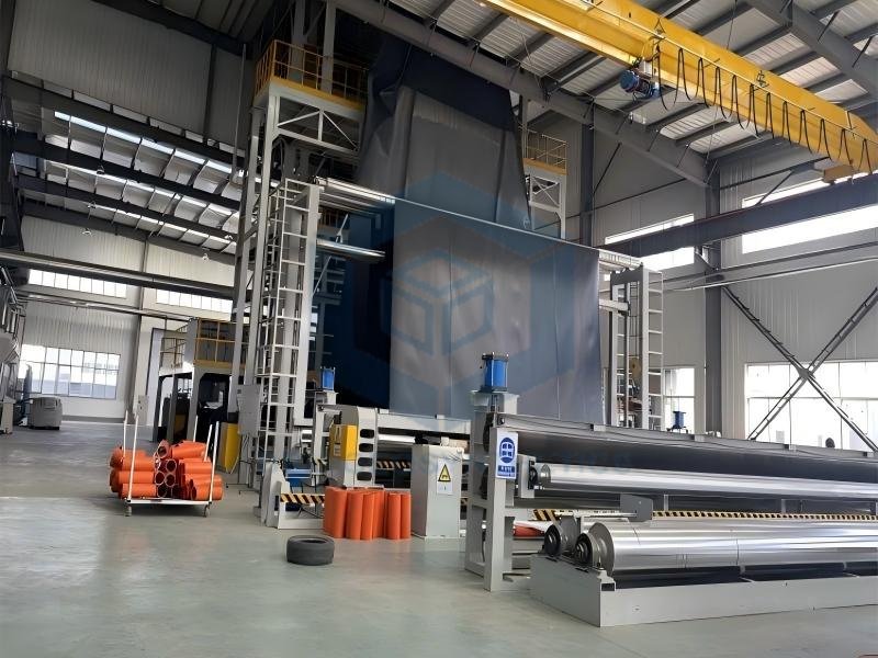
What Is an HDPE Liner and Why Installation Quality Matters
An HDPE liner is an impermeable geomembrane produced from high-density polyethylene resin with a formulated density ≥0.940 g/cm³. Typical thicknesses range from 0.75 mm to 3.0 mm (30–120 mil). Key performance attributes include tensile yield strengths that scale with thickness (e.g., ≥15 kN/m at 1.0 mm and ≥22 kN/m at 1.5 mm per ASTM D6693), elongation at break ≥700 percent, puncture resistance ≥320 N (1.0 mm) to ≥480 N (1.5 mm), and carbon-black content of 2.0–3.0 percent for UV stability.
Proper installation transforms these material properties into a continuous, leak-free barrier. Field experience demonstrates that well-executed installations achieve seepage reductions of 95–99.9 percent compared with unlined systems and maintain seam strengths ≥90 percent of parent-sheet values. Conversely, common installation errors can reduce effective service life by decades or create localized leakage pathways that compromise environmental compliance.
Types of HDPE Liners Relevant to Installation
Before beginning the eight steps, project teams must select the appropriate surface finish:
- Smooth HDPE Liners: Preferred for flat or gently sloping subgrades. They offer maximum chemical resistance, easiest welding, and lowest material cost. Ideal for pond bases, landfill floors, and secondary containment.
- Textured HDPE Liners: Feature asperities that increase interface friction angles (typically 25–35° or higher). Recommended for slopes steeper than 3H:1V, landfill side slopes, and mining heap-leach pads.
- Conductive HDPE Liners: Incorporate a conductive layer that enables electrical leak-location surveys (spark testing) after installation. Used on critical hazardous-waste or high-value containment projects.
BPM Geosynthetics supplies both smooth and textured grades that fully comply with GRI-GM13, allowing designers to match surface finish to site geometry while maintaining consistent mechanical and durability properties.
8 Steps to Ensure Successful HDPE Liner Installation
Step 1: Site Assessment, Planning and Material Verification
Successful installation begins long before the first roll is unrolled. Conduct a geotechnical investigation to confirm subgrade stability, bearing capacity, and groundwater conditions. Prepare detailed panel-layout drawings that minimize the number of field seams, avoid seams crossing at corners, and provide adequate material for anchor trenches (typically 500 mm deep × 500 mm wide).
Verify that delivered rolls match project specifications. Confirm thickness (ASTM D5199), density ≥0.940 g/cm³, carbon-black content 2.0–3.0 percent, and mill certificates showing GRI-GM13 compliance. Store rolls off the ground, protected from prolonged UV exposure and mechanical damage. Quantifiable planning targets include limiting daily deployment to the area that can be welded and tested the same day, reducing the risk of wind or temperature-related damage.
Step 2: Subgrade Preparation and Acceptance
Subgrade quality is the single most important factor affecting long-term liner performance. Industry surveys consistently identify inadequate subgrade preparation as the leading cause of puncture and stress-related failures.
Key measurable requirements include:
- Removal of all rocks, roots, vegetation, and debris larger than 20 mm.
- Surface smoothness within ±12 mm (or tighter project limits of ≤3 mm over 3 m).
- Compaction to a minimum 90–95 percent of standard Proctor density.
- Elimination of standing water and soft spots.
- Installation of a non-woven geotextile cushion (typically 200–400 g/m²) over rocky or angular soils to increase puncture resistance by 40–70 percent.
Proof-roll the finished subgrade with loaded equipment and obtain formal CQA acceptance before any liner deployment. A properly prepared subgrade distributes loads evenly and prevents localized stress concentrations that can initiate long-term stress cracking.
Step 3: Panel Layout, Measuring and Cutting
Accurate measurement and panel identification reduce waste and ensure correct orientation. Allow 75–150 mm overlap for welding (typically 100–150 mm for hot-wedge fusion). Provide extra material for anchor trenches and thermal contraction (HDPE expands and contracts significantly with temperature changes). Pre-label every panel with roll number, thickness, and orientation for full traceability.
Layout drawings should orient long seams parallel to the slope direction wherever possible and offset T-joints by at least 1.5 m. Proper layout can reduce total seam length by 15–30 percent on large projects, lowering both labor and risk.
Step 4: Controlled Deployment of the HDPE Liner
Deployment must protect the liner from mechanical damage and minimize wrinkles. Unroll panels in the direction of the slope, starting from the anchor trench whenever practical. Avoid dragging the material across rough surfaces. Use low-ground-pressure equipment and temporary sandbag ballasting to secure panels against wind. Limit daily deployment to the area that can be fully welded and tested before nightfall or adverse weather.
Ambient temperature and wind conditions significantly affect handling. Installation is generally suspended when wind speeds exceed safe working limits or when temperatures fall outside the range recommended by the welding equipment manufacturer (commonly 5–40 °C for reliable fusion).
Step 5: Welding – Hot-Wedge Fusion and Extrusion Seaming
Seaming is the most critical technical stage of HDPE liner installation. Primary field seams are produced by dual-track hot-wedge welding, which creates two parallel fusion tracks separated by an air channel that enables 100 percent non-destructive pressure testing. Extrusion welding is used for patches, repairs, pipe penetrations, and detail work.
Before production welding each day, and after any change in ambient conditions or machine settings, perform trial welds on scrap material. Test the trial samples in peel and shear according to ASTM D6392 and GRI-GM19a. Acceptable seams typically achieve film-tear bond (the parent sheet fails before the weld) and strengths ≥90 percent of the parent material.
Typical starting parameters for 1.0–1.5 mm HDPE (adjusted by trial welds) include wedge temperatures of 400–500 °C, travel speeds of 1.5–3.0 m/min, and roller pressures of 3–4 bar. Seam surfaces must be clean, dry, and free of dust or moisture; contamination can reduce weld strength by 20 percent or more.
Step 6: Seam Testing and Construction Quality Assurance
Every seam must be verified. Non-destructive testing covers 100 percent of dual-track seams via air-channel pressure testing (typically 25–30 psi / 170–200 kPa held for 5 minutes with allowable decay ≤10–20 percent). Vacuum-box testing (ASTM D5641) is used for extrusion welds and patches. Spark testing is available for conductive liners.
Destructive samples are cut at the frequency specified by the project CQA plan (commonly one sample every 150–500 linear meters of seam) and tested in both peel and shear. Documentation includes welding logs, machine settings, test results, and repair records. Independent third-party CQA oversight is strongly recommended for critical projects.
Step 7: Anchor Trench Construction and Perimeter Securement
The liner must be securely terminated in continuous anchor trenches around the entire perimeter. Typical trench dimensions are 500 mm deep by 500 mm wide, although project-specific geotechnical analysis may require larger sections on steep slopes or high-wind sites. The liner is placed into the trench, backfilled in controlled lifts, and compacted to prevent pull-out or excessive tension. Proper anchorage protects against wind uplift and thermal movement while maintaining the designed freeboard.
Step 8: Protective Cover Placement and Final Documentation
Once seams are accepted, install the protective cover system as soon as practical. A non-woven geotextile cushion is typically placed first, followed by soil, gravel, or other specified cover materials in controlled lifts using low-ground-pressure equipment. Avoid sharp stones and excessive drop heights that could puncture the liner.
Final inspection includes a complete visual survey, verification of all repairs, and compilation of the as-built documentation package (panel layout, welding logs, test results, material certificates, and CQA reports). This package is essential for regulatory acceptance and long-term asset management.
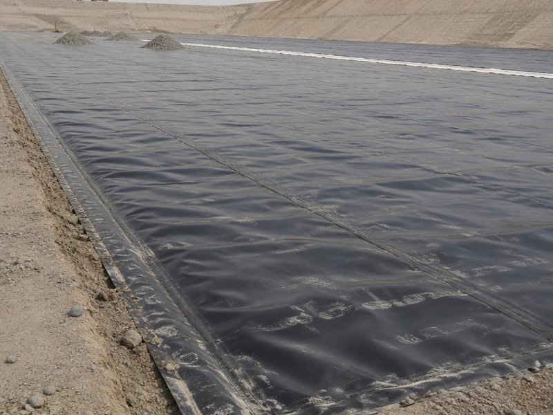
Comparison Tables
Table 1: Core Installation Parameters and Acceptance Criteria for HDPE Liner Systems
Parameter | Typical Value / Requirement | Test / Reference Standard | Engineering Importance |
Subgrade flatness | ≤3 mm over 3 m | Project / ASTM F710 | Prevents puncture and stress concentration |
Maximum stone size | ≤20 mm | Visual / CQA | Avoids puncture under load |
Panel overlap (fusion) | 100–150 mm | Project specification | Ensures continuous weld track |
Hot-wedge temperature (start) | 400–500 °C | Equipment / trial weld | Achieves full fusion without thinning |
Air-channel test pressure | 25–30 psi (170–200 kPa) | ASTM D5820 | 100 % non-destructive seam verification |
Air-channel hold time / decay | 5 min / ≤10–20 % | ASTM D5820 | Confirms continuous, leak-free channel |
Destructive peel / shear | ≥90 % parent or film-tear bond | ASTM D6392 / GRI-GM19a | Verifies bond strength |
Anchor trench (typical) | 500 mm × 500 mm | Project design | Resists pull-out and thermal movement |
Table 2: Material and System Performance Indicators Relevant to Installation Success
Attribute | GRI-GM13 / Typical Value (1.0–1.5 mm) | BPM Smooth HDPE Liner | Impact on Installation Success |
Density | ≥0.940 g/cm³ | ≥0.940 g/cm³ | Confirms HDPE classification and weldability |
Tensile yield (1.0 mm) | ≥15 kN/m | ≥15 kN/m | Handles deployment and thermal stresses |
Puncture resistance (1.0 mm) | ≥320 N | ≥320 N | Survives residual subgrade irregularities |
Elongation at break | ≥700 % | ≥700 % | Accommodates settlement and wrinkles |
Standard / HP-OIT | ≥100 / ≥400 min | ≥100 / ≥400 min | Long-term oxidative stability after installation |
Carbon black | 2.0–3.0 % | 2.0–3.0 % | UV protection during temporary exposure |
Certifications | GRI-GM13 | GRI-GM13, ISO 9001/14001 | Traceability and regulatory acceptance |
Common Mistakes That Compromise HDPE Liner Performance
Avoid the following frequent errors:
- Inadequate subgrade preparation or acceptance.
- Welding in rain, high humidity, or outside recommended temperature ranges.
- Insufficient seam overlap or contaminated weld zones.
- Skipping daily trial welds or non-destructive testing.
- Prolonged UV exposure before protective cover placement.
- Using high-ground-pressure equipment on unprotected liner.
- Incomplete documentation and as-built records.
Professional installation following the eight steps above dramatically improves reliability and reduces long-term risk.
The Best Project Material Co., Ltd (BPM Geosynthetics) Advantages
The Best Project Material Co., Ltd (BPM Geosynthetics) manufactures Smooth and Textured HDPE Geomembranes that fully comply with GRI-GM13 across the 0.75–3.0 mm thickness range. The products are produced from 100 percent virgin resin with 2.0–3.0 percent premium carbon black, delivering consistent density ≥0.940 g/cm³, tensile properties that meet or exceed the minima listed above, puncture resistance scaled to thickness, and high-pressure OIT ≥400 minutes.
Wide roll formats (commonly 7–8 m) reduce the number of field seams, lowering both installation time and risk. ISO 9001 and ISO 14001 certified manufacturing provides full batch traceability and third-party test documentation. BPM Geosynthetics supplies technical support for welding parameter selection, trial-weld procedures, and project-specific CQA guidance. For projects requiring a reliable material platform that supports successful HDPE liner installation, BPM Geosynthetics offers a high-performance, fully certified solution. Contact sales@bpmgeosynthetics.com or visit the product page for data sheets, samples, and formal quotations.
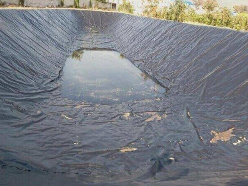
Conclusion
Successful HDPE liner installation is a controlled engineering process, not a simple construction activity. The eight steps outlined—site assessment and material verification, subgrade preparation, panel layout, controlled deployment, professional welding, comprehensive seam testing, anchor-trench securement, and protective cover with full documentation—collectively determine whether the installed system will deliver its designed 50–100 year service life and near-zero seepage performance.
By adhering to quantifiable criteria drawn from GRI-GM13, ASTM standards, and industry best practice, project teams can minimize the most common failure modes and achieve regulatory and operational success. When these installation disciplines are combined with a high-quality, fully documented HDPE geomembrane such as that supplied by The Best Project Material Co., Ltd (BPM Geosynthetics), owners and engineers gain confidence in long-term containment integrity.
For technical assistance, welding parameter recommendations, or project-specific quotations, contact BPM Geosynthetics. Proper material selection and rigorous installation remain the two indispensable pillars of reliable HDPE liner performance.